How To Install Allen Bradley 700-ar1, The Allen-Bradley 700-AR1 manual provides essential information for correctly installing and operating the relay. This relay, manufactured by Rockwell Automation, is widely used in industrial control systems for efficient switching applications. Understanding the Allen-Bradley catalog helps in selecting the appropriate model for specific requirements.
Whether you are setting up the Allen-Bradley 700-AR1 starter or integrating it into a control panel, following the correct procedures ensures smooth functionality. With careful attention to wiring, mounting, and testing, the relay can be successfully installed. Following the Allen-Bradley 700-AR1 manual ensures compliance with safety regulations and manufacturer guidelines.
Required Tools and Materials for Installation
To install the Allen-Bradley 700-AR1 starter, you need specific tools and materials for proper setup. The Allen-Bradley catalog lists compatible accessories that might be required, such as mounting brackets, terminal blocks, and additional connectors. A flathead screwdriver and a Phillips screwdriver are necessary for securing connections and mounting the relay.
The Allen-Bradley 700-AR1 manual recommends using insulated wire cutters and strippers for precise electrical connections. For safety, ensure that you have insulated gloves and a multimeter to test the voltage levels. Proper wiring ensures that the Allen-Bradley 700-AR1 power system functions efficiently without risks of electrical faults.
Industrial control panels often require DIN rail mounting, which means you may need mounting clips and screws. Since different configurations exist within the Allen-Bradley 700-AR1 series, check the relay’s voltage and current ratings before installation. Having the correct wire gauge is essential to match the relay’s specifications. Always refer to Rockwell Automation guidelines for tool selection and best practices.
Understanding the Wiring Diagram
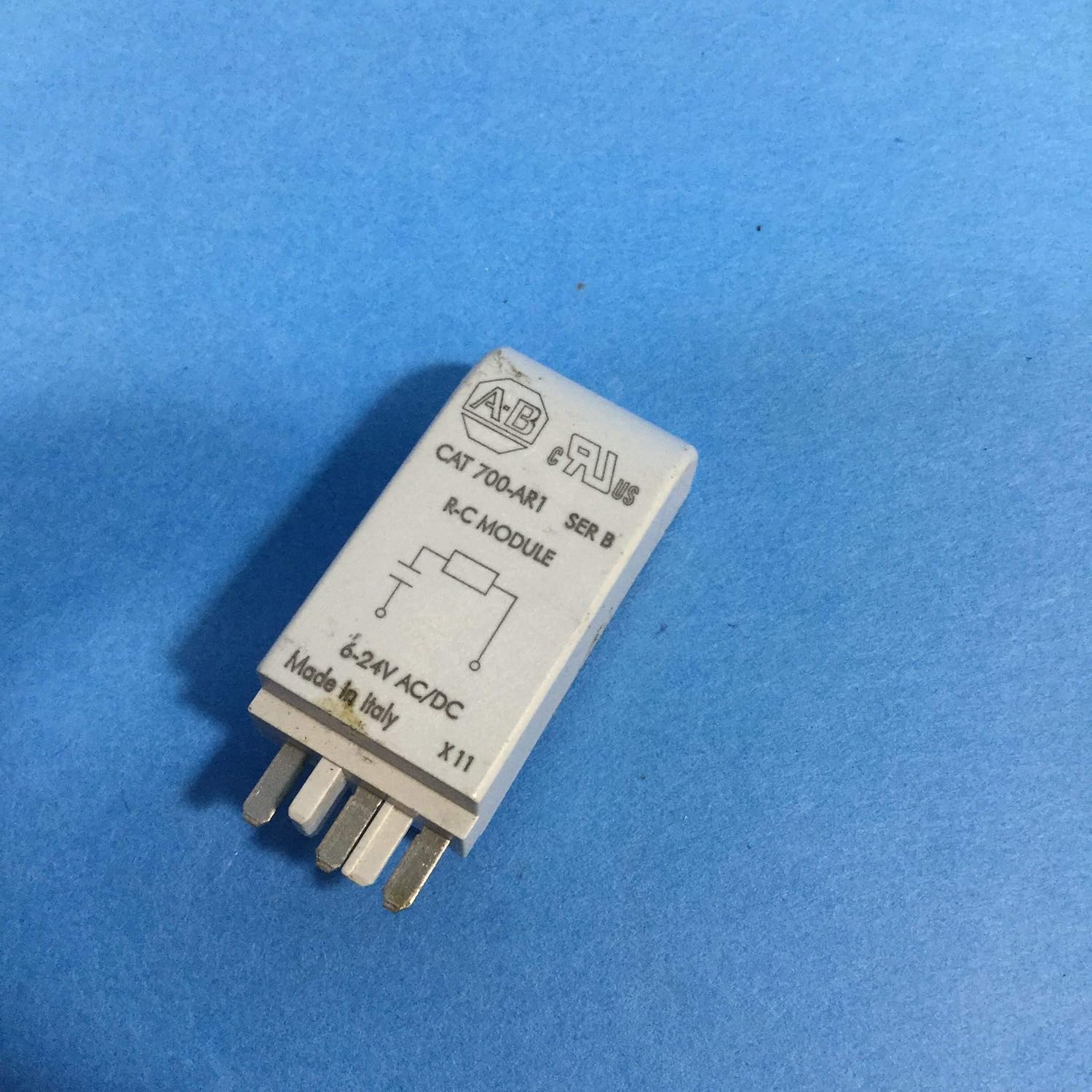
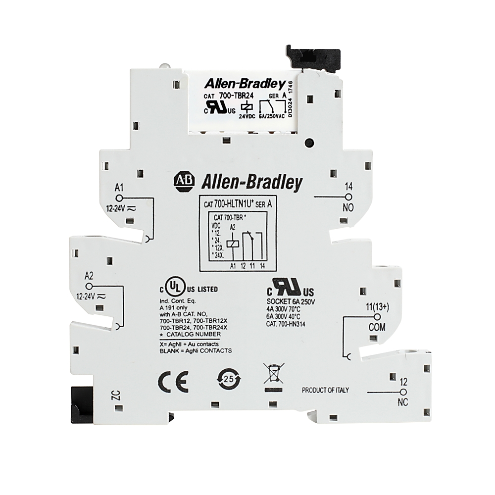
Before installing the Allen-Bradley 700-AR1 starter, it is crucial to understand its wiring configuration. The Allen-Bradley 700-AR1 manual provides detailed diagrams showing terminal connections and relay contacts. The relay typically consists of a coil circuit and multiple contact points, which facilitate electrical switching.
In industrial setups, the relay may be part of a motor control system that integrates with other components from the Allen-Bradley catalog. The wiring diagram explains how the Allen-Bradley 700-AR1 power circuit connects to the control and load side. Depending on the Allen-Bradley 700-AR1 series, the relay may have different voltage ratings, requiring careful connection to prevent overloading.
The wiring should follow the polarity instructions to ensure proper functionality. Each terminal must be correctly identified to avoid short circuits or misconfigurations. Always refer to Rockwell Automation technical documents to confirm the correct wiring method. Properly following the diagram ensures the relay operates efficiently and safely.
Mounting the Relay in the Panel
Installing the Allen-Bradley 700-AR1 starter involves securely mounting the relay inside an electrical panel. According to the Allen-Bradley 700-AR1 manual, the relay should be positioned in a well-ventilated area to prevent overheating. The Allen-Bradley catalog provides details on compatible DIN rail mounting accessories.
Ensure that the panel surface is clean and free from obstructions before placing the relay. The Allen-Bradley 700-AR1 power connections should be easily accessible for wiring. Different models within the Allen-Bradley 700-AR1 series may have varying mounting requirements, so checking specifications is essential.
Secure the relay with appropriate screws or mounting brackets as per Rockwell Automation standards. The relay should be positioned in an upright manner for optimal heat dissipation. Double-check alignment before tightening the mounting screws. Once mounted, proceed to connect the electrical wires as per the wiring diagram.
Connecting the Electrical Wires Properly
Proper wiring is essential for the Allen-Bradley 700-AR1 starter to function correctly. The Allen-Bradley 700-AR1 manual provides terminal assignments for connecting input and output circuits. The Allen-Bradley catalog recommends using correctly rated wires to handle the relay’s current capacity.
The Allen-Bradley 700-AR1 power terminals must be securely tightened to prevent loose connections. In different models of the Allen-Bradley 700-AR1 series, input and output terminals may vary slightly. Ensure that the coil voltage matches the control voltage of your system.
Double-check the terminal numbers before finalizing the connections. Follow Rockwell Automation guidelines for grounding to avoid electrical faults. Once wired, conduct an initial continuity test to verify the proper connection. Incorrect wiring can lead to relay malfunction or system failure.
Testing and Verifying the Connections
After installation, testing the Allen-Bradley 700-AR1 starter is crucial to ensure proper functionality. The Allen-Bradley 700-AR1 manual recommends using a multimeter to check voltage levels before powering the system. The Allen-Bradley catalog lists standard testing procedures to confirm relay performance.
Apply control voltage to the Allen-Bradley 700-AR1 power circuit and observe the relay’s operation. For models within the Allen-Bradley 700-AR1 series, ensure that the contact switches operate correctly under load conditions. If the relay does not activate, recheck the wiring connections. Rockwell Automation suggests verifying that the coil voltage is within the rated range. Perform multiple switching cycles to confirm reliability. If the relay passes all tests, proceed to secure the panel and finalize the installation.
Troubleshooting Common Installation Issues
Issues with the Allen-Bradley 700-AR1 starter can often be resolved with systematic troubleshooting. The Allen-Bradley 700-AR1 manual suggests checking for loose connections or incorrect wiring. The Allen-Bradley catalog provides fault codes for diagnosing relay malfunctions.
If the Allen-Bradley 700-AR1 power supply is inconsistent, verify voltage input levels. Some models in the Allen-Bradley 700-AR1 series may require additional configuration settings. If the relay is overheating, check for proper ventilation as per Rockwell Automation guidelines.
Final Checks and Safety Precautions
Before using the Allen-Bradley 700-AR1 starter, ensure all connections are properly secured. The Allen-Bradley 700-AR1 manual advises double-checking terminal screws for tightness.
Refer to the Allen-Bradley catalog for recommended safety standards. Verify that the Allen-Bradley 700-AR1 power source is stable and meets the required specifications. Different Allen-Bradley 700-AR1 series models may have unique safety considerations. Rockwell Automation emphasizes grounding to prevent electrical hazards.
Frequently Asked Questions
How do I know if the relay is working properly?
Check the relay operation by applying the control voltage and listening for a clicking sound. Use a multimeter to verify voltage across output contacts.
What voltage is required for the coil?
The Allen-Bradley 700-AR1 manual specifies different coil voltages, typically 24V DC or 120V AC. Always confirm the voltage before wiring.
Can I use this relay for motor control?
Yes, the Allen-Bradley 700-AR1 starter is designed for industrial motor control applications. Ensure proper wiring and contact rating for the motor load.
What should I do if the relay doesn’t activate?
Check the Allen-Bradley 700-AR1 power supply and verify the coil voltage. Ensure wiring is connected as per the Allen-Bradley 700-AR1 manual.
Where can I find additional technical support?
The Allen-Bradley catalog and Rockwell Automation website provide extensive documentation. You can also contact technical support for assistance.
Conclusion
Installing the Allen-Bradley 700-AR1 starter requires careful attention to wiring, mounting, and safety precautions. Always refer to the Allen-Bradley 700-AR1 manual for manufacturer guidelines.
The Allen-Bradley catalog provides details on compatible accessories and specifications. Ensuring a stable Allen-Bradley 700-AR1 power supply is critical for optimal performance.